How to Systematically Analyze your Optical System in VirtualLab Fusion
VirtualLab Fusion delivers fast and accurate optical simulations, but like any simulation software, may produce artifacts.
To ensure reliable results or conduct systematic investigations, we recommend the following workflow.
View Light Propagation through the System
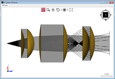
The 3D System View visualizes light propagation as rays throughout the system, providing a quick overview of potential issues like clipping, absorption, or
multiple reflections. The Ray Results Profile does not include field information and omits certain diffractive effects (like from e.g. DOEs) but effectively shows whether the light path behaves as expected.
Figure 1: 3D System View revealing the presence of multiple internal reflection in a lens system and where they stem from
The 3D System View can be simulated by activating the Ray Result Profile and the System:3D button in the Profile Editing & Run - section of the main
ribbon.
Frequently Asked Questions (FAQ)
- ”I do not see light paths where I expect them to be.”
Please follow this link: System 3D View
Determine Fourier Transform Settings
For field propagation, activate the General Profile and Detectors buttons.
Fourier Transforms are critical for electromagnetic field calculations. These can be adjusted in the Profile Editing Tools under the Profile Edition & Run tab. An overview of which Fourier Transform setting corresponds to which propagation method can be found here: Fourier Transforms in VirtualLab Fusion. As a rule of thumb, using the pointwise operator significantly speeds up simulations but may yield inaccurate results near interfaces close to a focus due to ignored diffraction effects. If there is no obvious point where diffraction effects need to be handled carefully (such as e.g. a detector in the focal plane), simulating the system with pointwise operators might already produce statisfactory results really fast. Comparing the results obtained by different configurations allows the user to further optimize the system to be as accurate as necessary but as fast as possible.
Figure 2: Field near the focus of a spherical lens simulated by different Fourier Transform settings. A fast simulation with only pointwise operators reveals the
size of the beam but no details. Using automatic operator for the propagation step towards the detector already includes most of the diffraction effects, while
using automatic operator everywhere is the slowest but also the most accurate result.
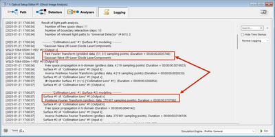
The software features a powerful logging tool that details the Fourier Transforms used in the simulation at each step, along with the rationale behind their selection.
Frequently Asked Questions (FAQ)
- ”VLF uses pointwise fourier transform, but I expect it to not be valid.”
Please check if the Enforce Pointwise Fourier Transform parameter is active. Link: Speed vs Accuracy Tool
- ”Can I enforce a rigorous Fourier Transform?”
This can be done using the following tool: Pointwise vs Integral Operations
Detection of the Electromagnetic Field
The output of the simulation obviously depends on the used detector. While VirtualLab Fusion provides many different detector types for this assistant entry,
we want to focus on the most flexible and the one we recommend; the Plug-In Detector.
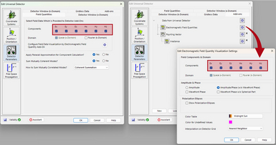
Depending on the to-be-investigated light criteria, in order to obtain a reasonable result, it is essential to ensure that the detector captures all necessary field components accurately before proceeding with other calculations. An incorrect configuration may lead to false results. The detector field components can be set up in the Plug-In Detector itself.
Frequently Asked Questions (FAQ)
- ”Why is the z-component of my field always zero?”
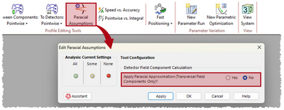
When the z-component of the electric field is zero, it may be due to a Paraxial Assumption. If this is undesired, you can disable it in the Profile Editing & Run tab of the main ribbon.
Sampling & Accuracy Parameters
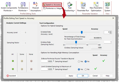
In addition to the sampling parameters within the detector, VirtualLab Fusion provides advanced accuracy controls accessible via the Speed vs Accuracy tool in the Profile Editing & Run tab of the main ribbon.
The tool comprises two sections: Hybrid Sampling Configurations and Options for Handling High Memory Consumption:
- Hybrid Sampling Configurations: These settings allow for internal adjustment of sampling parameters for propagation operators. Detailed definitions can be found here. For general use, you can increase the levels incrementally to ensure the convergence of the results.
- Handling High Memory Consumption: These options address simulations that exceed your computer’s RAM capacity and keep in mind that these limitations may impact accuracy if higher sampling efforts are absolutely required.
These options are:- Enforce Pointwise Fourier Transform: Automatically switches to pointwise operators when the sampling rate is too high. May compromise physical accuracy.
- Limit Gridded Sampling to Maximum: Uses the rigorous Fourier transform while capping the maximum sampling points, potentially introducing numerical noise.
To ensure authentic result, turn both options off and test if the result remain the same. Please be aware however, that this potentially may increase the necessary computational effort depending on the task at hand.
