
Missing Light in Your System 3D Result?
It might happen that the 3D result window of the Ray Results Profile simulation does not show the expected light (paths). This document lists several possible
reasons for this by explaining different aspects of the configuration of an optical setup.
Element Size, Orientation and Positioning
If certain rays are missing in the System 3D Result window, often the reason is that they do not encounter another element due to its dimension, position, and/or orientation. The figures in this section show some examples.

Figure 1: Light going through a concave lens reaching a small and large detector.

Figure 2: Reflection on a silver sphere. The red marking indicates the orientation of the infinite detector in the far field. On the left side, some rays would never hit the detector due to their reflection angle, even in infinity. Thus, their reflection is not shown.
The size of the elements may be specified differently depending on the element type (see figure 3).
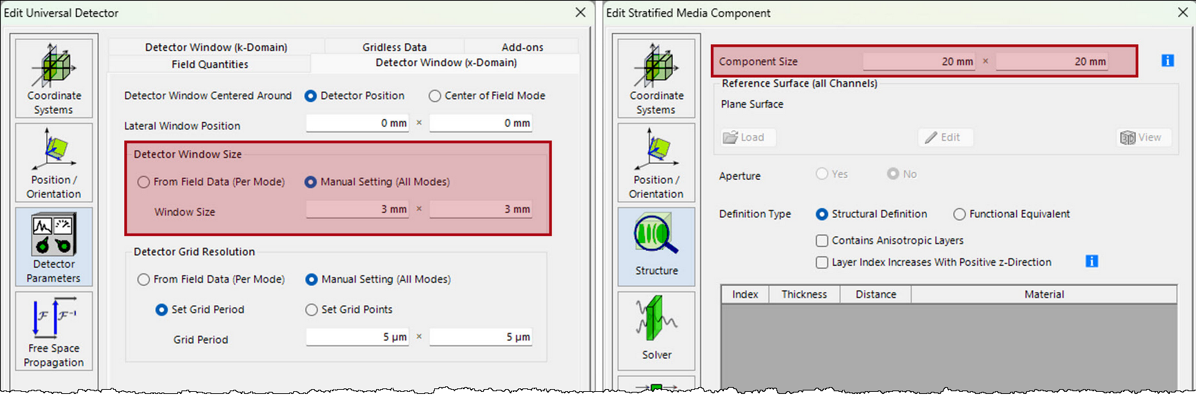
Figure 3: Two examples where/how to define an element’s size.
Another cause could be the usage of ideal elements whose effect is infinite (see figure 4).

Figure 4: Illustration of system with two light paths, where an aperture element in the upper light path is blocking the lower light path due to its infinite definition.
Furthermore, it is a good idea to check the orientation of the coordinate system of all elements. This is crucial for determining which channels should be open (see section 4) and for handling media transitions, as new media are typically defined behind a surface.
Note that most detectors only process light arriving along the positive z-direction of their coordinate system. So, like in the real world, a sensor that looks in the wrong direction will show an empty or unexpected output. If such detector exhibits such a wrong orientation, then VirtualLab Fusion (VLF) will not show any rays towards this detector. For an in-depth tutorial on how to position and orientate elements in VirtualLab Fusion, please see: Tutorial: Position and Orientation of Elements
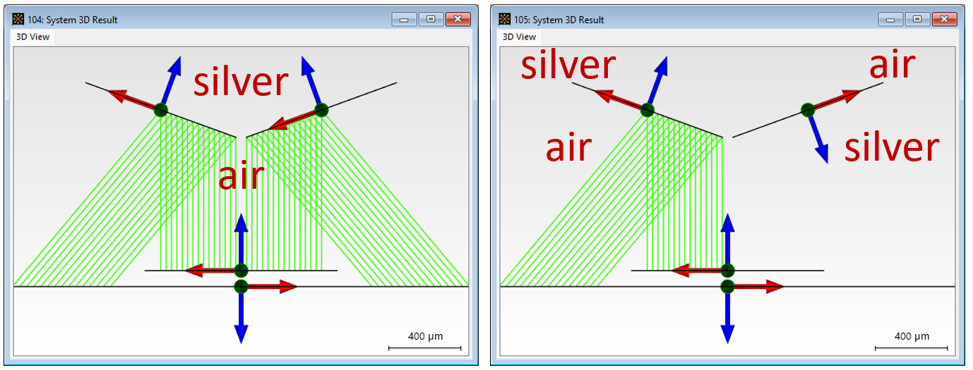
Figure 5: Simulation of a silver wedge, represented by two tilted surfaces, in a system in manual configuration mode (regarding the configuration modes, please see section 2). Both surfaces are specified by having air in front of them and silver behind them. On the left side, everything functions as expected. On the right side due to an incorrect orientation of the right mirror, the reflected light there is missing.
Configuration of the Light Path Finder
If it is about missing light from a system, which is meant to simulate non- sequential light paths, it is worth checking if the correct configuration mode is selected and its options appropriately set. VirtualLab Fusion provides the user with two configuration modes, the Pre-Selected and the Manual Configuration (see figure 6).
- If the Pre-Selected Configuration is used, VirtualLab Fusion considers only light propagations from one system element to the next according to the defined linkages in the Optical Setup (OS).
- If the Manual Configuration is used, the so-called Light Path Finder is applied, which determines the propagation of light through the system according to the selected open channels. For this channel concept, please refer to section 4.
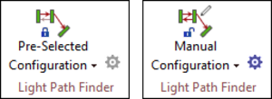
Figure 6: Available configuration modes (in Profile Editing & Run ribbon) determining if VirtualLab Fusion regards the system in a sequential or non-sequential way.
Diffraction Inducing Optical Elements
Generally, light propagation caused by diffraction is not taken into account in geometric optical simulations. The Ray Results Profile is primarily calculated point-by-point (pointwise), which corresponds to the geometric approximation of light propagation, so it is not expected that diffracted light will be shown in the system 3D result (from the Ray Results Profile). By default, VirtualLab Fusion will show the light corresponding to the zeroth order of diffraction, which, in the case of diffraction inducing optical elements, often simply corresponds to a transmission following the law of refraction, possibly clipped or attenuated, but otherwise unaffected.
There are exceptions, however: Some diffraction components allow you to explicitly specify which diffraction orders are to be simulated. These are elements where the direction in which the light is deflected can be derived from clearly defined periodic conditions via the grating equation. When using these components, such diffraction-generated light paths can also be considered in the Ray Results Profile. The user only needs to ensure that the orders to be considered are also set (see figure 7).
If the desired orders are not visible in the simulation results despite the correct settings, it may be because
- these orders do not physically exist (the deflection angle is greater than 90° to the diffractive surface).
- the energy of these orders is below the set limit. This can only happen in the Manual Configuration mode, where thresholds can be defined depending on the calculated energy or number of regarded surface interactions (see figure 8). Concerning these thresholds, see also section 5.

Figure 7: Edit dialog of the grating component: On the Channel Configuration page it can be seen, that by default only the zeroth order is specified for the transmission along the positive z-axis of the grating’s internal coordinate system. For simulating also other existing orders, these have to be added here.
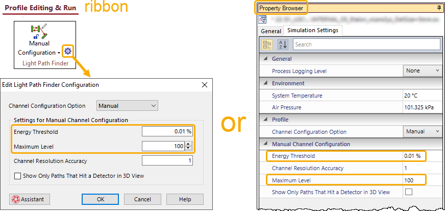
Figure 8: Two ways to set thresholds in the Manual Configuration mode: For the active Optical Setup, the user can set thresholds, to define, which (Energy Threshold ) or how many (Maximum Level ) light paths are taken into consideration.
Channel Configuration
As mentioned above, the reason for missing light might be that the channels are not appropriately set. In Manual Configuration mode, the user can define which channels should be considered for each component. A detailed explanation of the channel system can be found via the following link:
Channel Configuration
In summary, each surface typically has four channels: two channels to determine whether it is reflective, transmissive, or both for light paths entering from the front, and two more for light paths entering from the back. Based on the selected channels, the actual physical light propagation, and the set thresholds (see section 5), the Light Path Finder determines the light paths to be simulated.
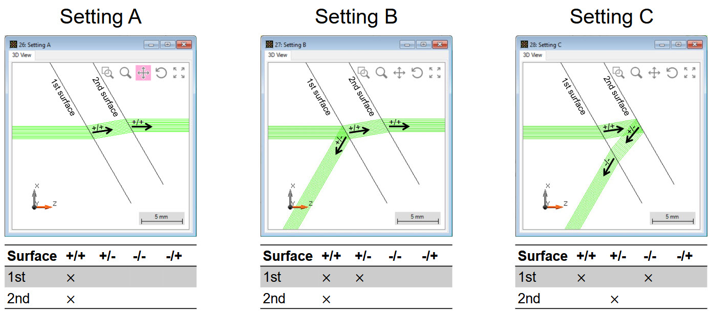
Figure 9: Examples of different channel configurations and their simulation results.
Each component’s edit dialog has a separate Channel Configuration page for the specification of the channels of interest (see figure 10).
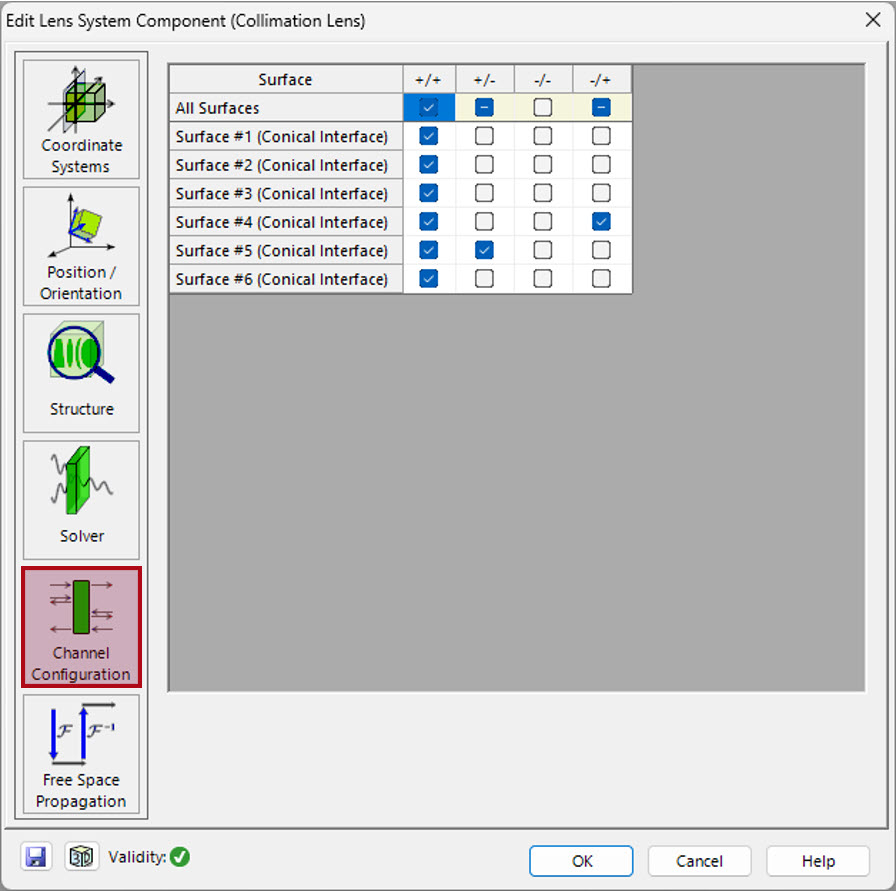
Figure 10: Channel Configuration page of a Lens System component.
When gratings or components with regions (e.g., lightguides) are present in the system, there are also channels per (grating) order or region, which can be activated or deactivated. For more information on this topic, please refer to the corresponding tutorial via the following link:
Tutorial: Channel Settings for Non-Sequential Tracing
Energy Threshold & Maximum Level
Sometimes expected light paths are not shown because of some set thresholds. In VirtualLab Fusion there are two thresholds that limit the number of considered light paths.
- The Energy Threshold filters out light paths below a certain energy level.
- The Maximum Level limits the number of interface interactions of each sequentially regarded light propagation.
These control parameters can either be set via the cogwheel button of the Manual Configuration in the Profile Editing & Run ribbon or via the Property Browser’s tab Simulation Settings (see figure 8). Figure 11 shows the effect of differently set energy threshold values.
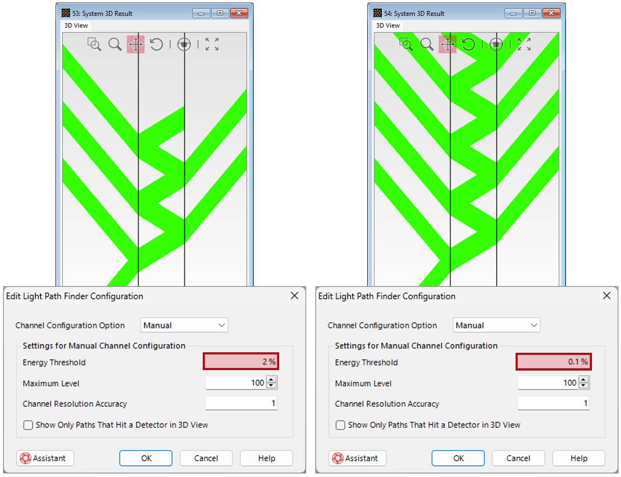
Figure 11: Etalon with 2 semi-transparent mirrors: The left depiction shows the system’s simulation with the Energy Threshold set to 2% whereas the right depiction shows it with a reduced value of 0.1%.
Light Paths that Never Reaches a Detector
In Manual Configuration mode, there is one more option that influences the display of rays in the system 3D result. It is called Only Show Paths that Hit a Detector in 3D. Like the thresholds previously discussed, it can be set either via the Manual Configuration edit dialog or via the Property Browser’s tab
Simulation Settings. By default, it is activated and, as the name suggests, only those rays will be shown, whose effect would also be seen by any detector of the
system (see figure 12). For the investigation of light paths that never reach a detector, please deactivate this checkbox.

Figure 12: Etalon system with detector having a window size of 5 mm × 5 mm. Depending on whether the option Only Show Paths that Hit a Detector in 3D is enabled or not, the system 3D result will look like either the left or the right image.