

Connecting Solvers by Master Channels
Author Frank Wyrowski (August 06, 2021)
VirtualLab Fusion enables fast physical-optics system modeling by connecting different solvers instead of applying one universal solver to the entire system [Kuhn2013]. This technology is enabled by a channel concept. The Light Path Finder in VirtualLab Fusion (see Step-by-Step Field Tracing with Modeling Analyzer) searches for channel surfaces with finite extent which are placed in space. The channel surfaces define the entrance into components and detectors. Often the surfaces form real interfaces between two media, but that is not required. They can be mathematical surfaces only with surface add-ons.
Channel surfaces are restricted to charts of height profiles. General surfaces can be built by combining them. In VirtualLab Fusion the Single Surface Components form the most basic type of components. They come with a planar or curved channel surface and optional surface add-ons like coatings, stacks, and functions. The single surface may also constitute an optical interface between two media. Then we must assume that light is blocked outside of the domain of the surface to obtain a consistent media transition in space.
The domain of the channel surface has rectangular or elliptic shape and forms the master channel region. Fig. 1 shows the dialogue of the settings for a channel surface.
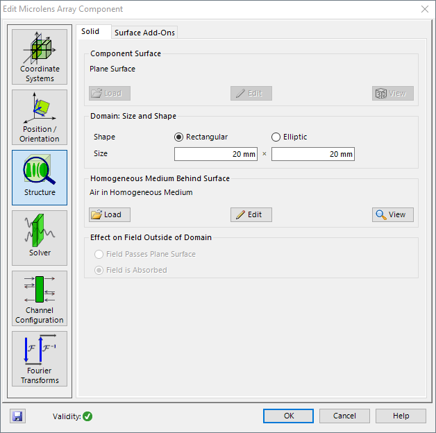
Light may hit the channel surface from both sides. Relative to the normal vector of the surface that defines (+) and (-) directions. Per direction a field response operator, which is associated with the channel surface and its add-ons, provides a reflected and a transmitted field response. Thus, we obtain four master channels which are associated with any channel surface. They are the transmission channels (+/+) and (-/-) and the reflection channels (+/-) and (-/+).
The master channels can be configured in any component and by that the degree of non-sequential modeling can be fully customized if the option Manual Settings is selected in the Channel Configuration as it is shown in Fig. 2 (Ribbon) and Fig. 3 (Property Browser).
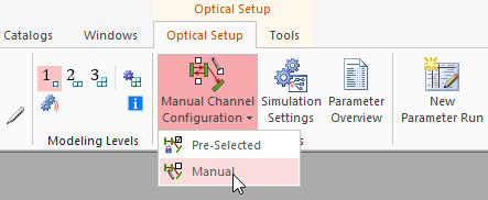
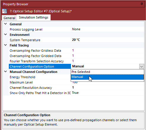
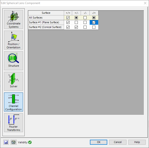
Figure 4 shows an example of the channel configuration of a lens with two surfaces. The shown configuration includes reflections and by that the investigations of ghost images in ray tracing and physical optics modeling, e.g., the effect of multiple reflections on the PSF/MTF.
- M. Kuhn, F. Wyrowski, and C. Hellmann, ‘Non-sequential Optical Field Tracing’, in Thomas Apel & Olaf Steinbach, ed., ‘Advanced Finite Element Methods and Applications’, Springer Berlin Heidelberg, pp. 257-273 (2013); https://doi.org/10.1007/978-3-642-30316-6_12