Step-by-Step Field Tracing with Modeling Analyzer
Author: Frank Wyrowski (August 5,2021)
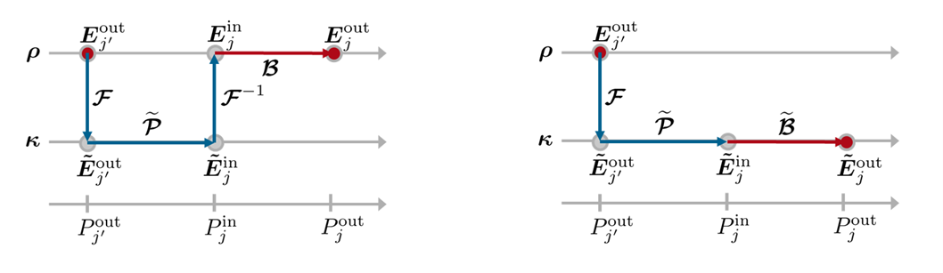
Physical-optics modeling in VirtualLab Fusion is initialized by the light path finder algorithm, which searches for all possible light paths through the system for a given configuration of component channels. That may result in a single light path or a complicated tree of light paths with hundreds and more light paths. The light paths form a tree the tip of which represents the source. The light path tree is processed starting from the source modes through the component channels to detectors. Each channel is modeled by a field response operator B which mathematically represents the solver of a given component structure or a functional effect without connection to a physical structure. Field response operators may work in space- or k-domain. Channels are connected by propagating the output field of one channel to the input of the next channel or to a detector. Thus, processing a light path means to follow from the output of the source to the inputs of channels and then from their outputs to the next channels and detectors. Figure 1 illustrates the propagation from a channel or source output in x-domain through the next channel with response operator in x-domain (left) and response operator in k-domain (right).
The Modeling Analyzer provides all input and output fields in x- and k-domain in the processing of the light path tree in the sequence of processing. That offers the user an unprecedented insight in the numerical and physical properties of all operation steps. We recommend restricting the number of light paths by the configuration of the channels when applying the Modeling Analyzer. That helps to focus on the operations of concern.
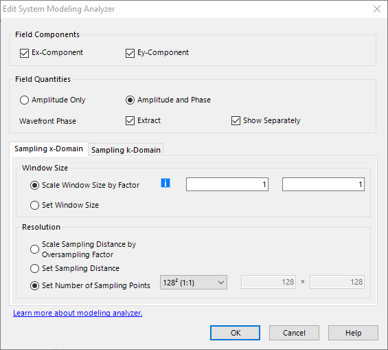
Figure 2 shows the settings dialogue of the Modeling Analyzer. It looks like most field-related detectors. It gives access to the settings in x- and k-domain. The use of the automatic selection of the window size is the suitable choice in most situations since the field size changes when it is propagated along the light paths. The analyzer provides access to the x- and y-component of the electric field. The wavefront phase can be extracted and shown separately.
When running the Modeling Analyzer, the system is modeled, and the complex field components at all inputs and outputs are provided in one window and the extracted wavefront phases in a second window when the option Show Separately is selected.
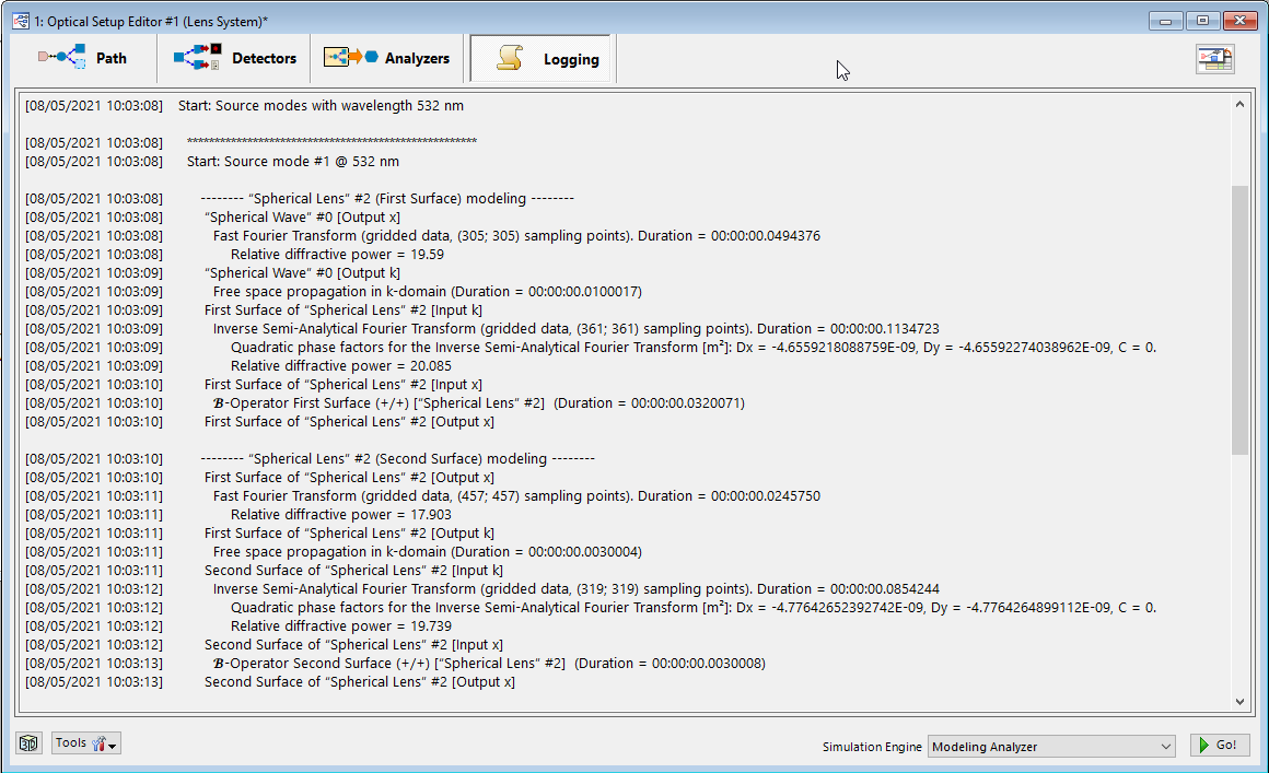
Running the Modeling Analyzer provides, as any modeling in VirtualLab Fusion, a logging which is depicted in Fig. 3 for an example. The logging provides a detailed insight into the processing, the selected operations, the sampling, and the computation time. We steadily develop the logging to give our users full transparency of the modeling process.
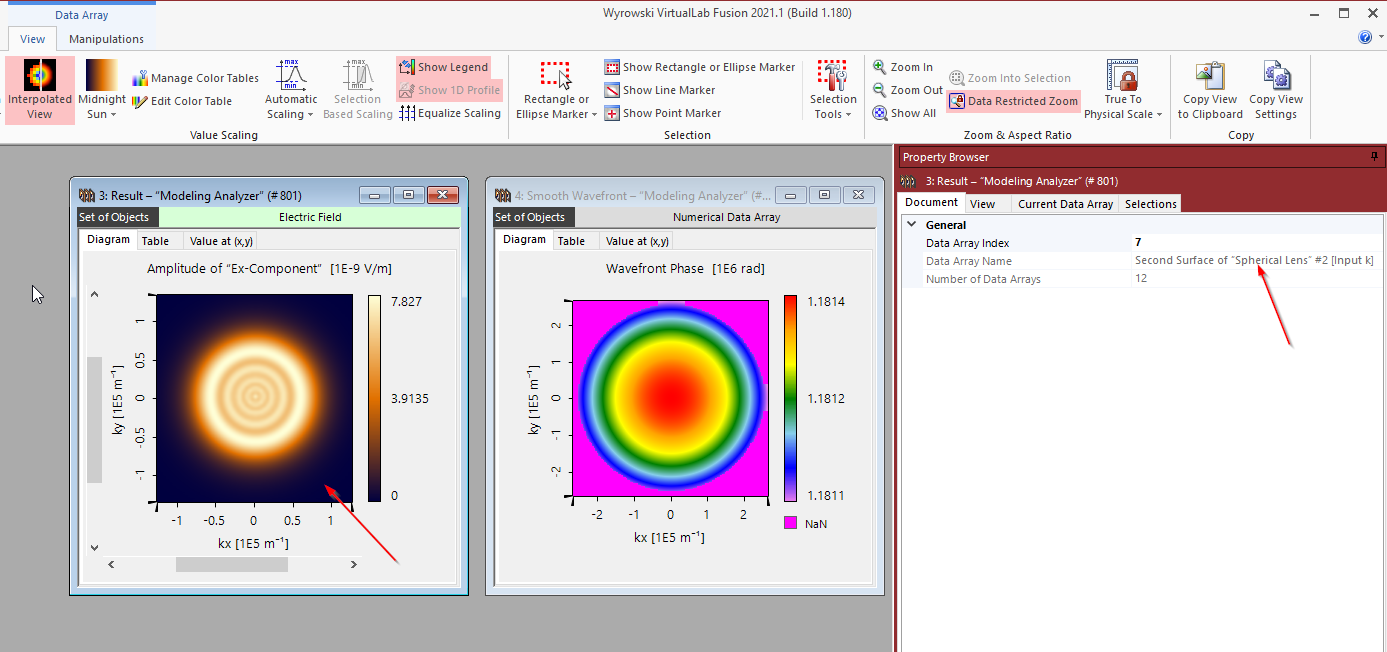
In the logging we use the notation of input and output fields per channel, e.g., Second Surface of “Spherical Lens” #1 [Output x]. The operations on the input fields are given in the logging as well. The same notation for the input and output fields is used in the naming of the fields in the result views of the Modeling Analyzer. That is illustrated in Fig. 4. The name of the field which is visible in the active Modeling Analyzer result window is shown in the Document tab of the Property Browser .
By clicking through the fields of the output view of the Modeling Analyzer, VirtualLab Fusion gives access to the fields as processed in the light path tree. That helps to understand the modeling and to identify operations which may lead to unreasonable results, e.g., because of undersampling. The identification of such operations helps to fix modeling challenges.