
Configuration of Grating Orders in Lightguides for Augmented Reality
Introduction
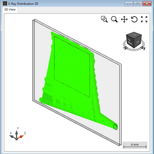
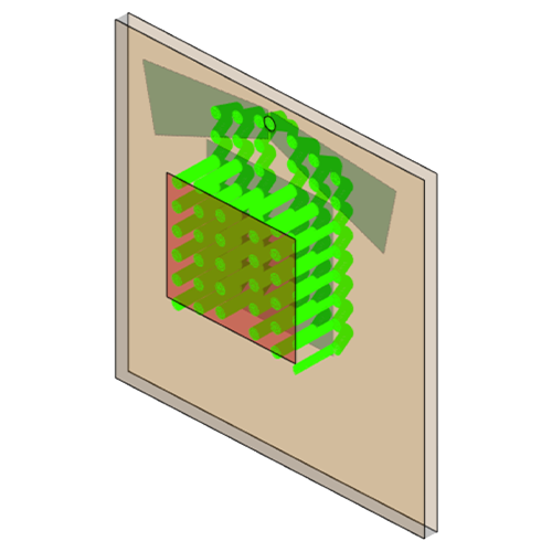
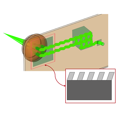
In many different architectures of augmented and mixed reality (AR & MR) devices, gratings play multiple different roles: coupling the light from the digital overlay into the lightguide under total internal reflection (TIR), generating several "replicas" of each finite-sized beam footprint to ensure that, wherever the observer is located within a certain region, some light from all the different pixels of the digital overlay will reach them (a technique typically known in the field as "Exit Pupil Expansion" or EPE) and coupling the light back out of the lightguide towards the observer.
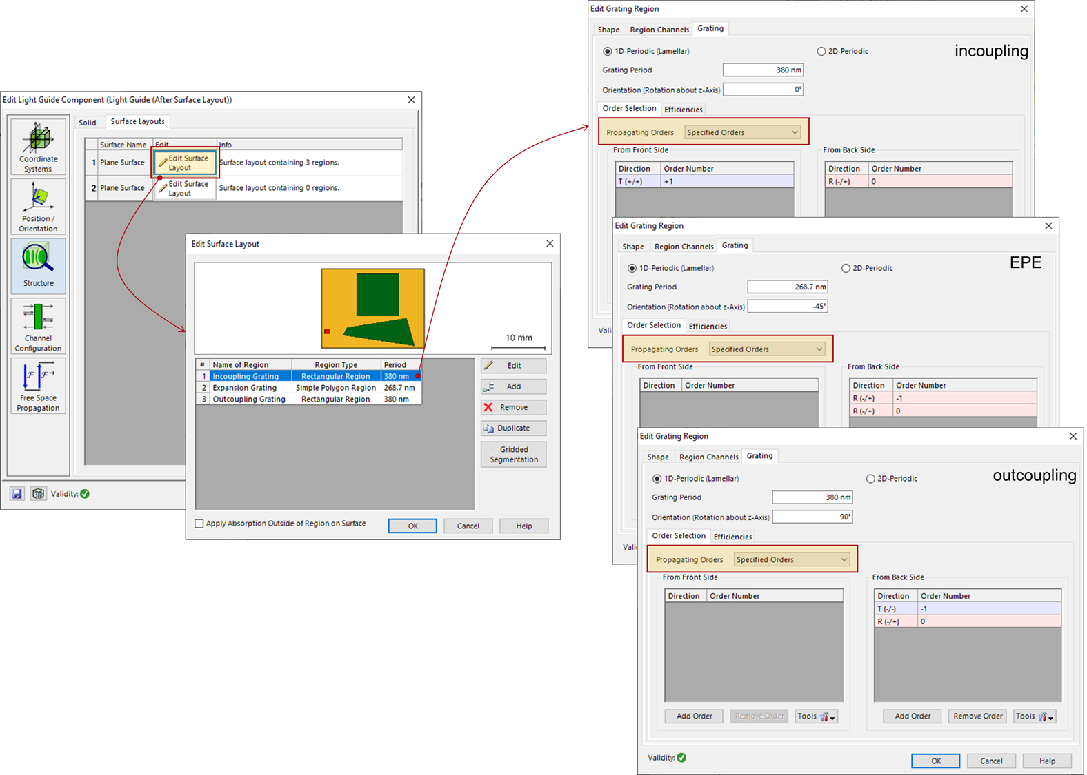
Typically, one or two of the diffraction orders from each grating region will be considered working orders, depending on the type of layout and the specific function performed in said layout by the grating region in question. Any other propagating orders generated by the gratings would be considered straylight.
In VirtualLab Fusion it is possible to manually configure which grating orders will be traced further in a simulation. This feature is particularly useful in the context of grating regions on lightguides for AR & MR, since the extremely high number of light paths bouncing back and forth under TIR can easily make the simulation time spiral out of hand.
Warning
This is why we strongly recommend configuring the grating orders carefully before running the simulation, making sure to limit their number as much as possible – ideally, leaving only the working orders whenever that is an option. You can control this from the Order Selection panel of each grating region on your lightguide (see figure below). Make sure to select the option Specified Orders from the drop-down list, otherwise additional orders may propagate!
In a 1D-1D-EPE layout, the working orders usually are:
- Incoupler: +/-1st transmitted (whether plus or minus depends on the specific geometry and orientation of the setup. We recommend using the k-Layout Visualization to determine which one is the working order in a specific design) order for light coming from the front, and 0th reflected order for light travelling backwards.
- EPE: 0th and +/-1st reflected orders for light coming from the back.
- Outcoupler: -/+1st transmitted order and 0th reflected order for light propagating backwards.
Example:
Use Case
Modeling of a HoloLens 1 - Type Layout with Light Guide Component
Use Case
Lightguide with Butterfly Eye-Pupil Expander based on Patent by Microsoft
Use Case