

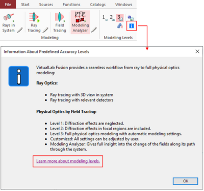
Seamless Transition from Ray to Physical Optics
We, the developers of VirtualLab Fusion, do not understand ray and physical optics as two disjunct modeling techniques between which the user must select. In our concept ray optics in form of ray tracing is a subset of physical optics modeling. With VirtualLab Fusion this is not an academic claim only, but we bring it to real life experience by a seamless and controllable transition between physical and ray optical modeling.
Theoretical Background
Fast physical-optics system modeling in VirtualLab Fusion is formulated by sequences of operators which mathematically represent the solvers. This way we connect solvers and we refer to it as connecting solvers by field tracing. Solvers may work in the x-domain and the k-domain. Fourier transforms connect the domains. It can be shown, that in situations in which the field which is to be Fourier transformed shows low diffraction effects, the integral Fourier transform (in form of the FFT) can be replaced by a pointwise Fourier transform [Wang2020]. This replacement is done automatically in VirtualLab Fusion in Modeling Level 3.
The criterion for switching between pointwise and integral Fourier transform is the relative diffractive power, which is a generalization of the Fresnel number.
By enforcing the pointwise Fourier transform in parts of the system, diffraction effects can be neglected independently of the relative diffractive power. This is done without leaving physical optics modeling in general and we still include e.g. interference, speckles, coherence, and polarization effects.
When all Fourier transforms in a system are enforced to be pointwise, diffraction is neglected in the entire system, and we often obtain a complete pointwise modeling in physical optics.
When we then just consider the mapping of positions of sampling points and connect them in the x domain, we obtain ray optics within physical optics [Baladron2019]. That can be understood as a derivation of ray tracing in the context of physical optics. We think this is an amazing piece of theory and it is the basis of ray optics in VirtualLab Fusion.
That leads us to the Modeling Levels 1 and 2 in which the pointwise Fourier transform is enforced in different parts of the system.
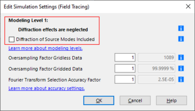
Modeling Level 1
In modeling level 1 diffraction is completely neglected by enforcing all Fourier transforms to be pointwise. This modeling is typically sufficient in applications in which light is not detected in focal regions, like light shaping in the far field [Yang2020], interferometer setups, and gratings for splitting beams.
If the source is a laser beam, it is typically recommended to select the Diffraction of Source Modes Included option. Consider as an example a Gaussian beam, which is defined in its waist. Then, its propagation over some Rayleigh lengths is dominated by diffraction. This is included by the Diffraction of Source Modes Included option which ensures Fourier transforms of initial source modes are automatically selected via the relative diffractive power.
Modeling Level 2
In modeling level 2 diffraction is carefully considered in all detector regions by selecting the Fourier transforms at detectors automatically via the relative diffractive power. This is of particular importance when detectors are in focal zones of the light, e.g., in the image or focal plane of a lens system [Wang2020]. In lens systems it provides high accurate calculation of point spread functions (PSF) and MTFs including diffraction, aberrations, polarization, and vectorial effects.
Level 2 is also suited when you investigate the light which is generated by microstructures.
If the source is a laser beam, also in Modeling Level 2 it is typically recommended to select the Diffraction of Source Modes Included option.
Modeling Level 3
In the highest modeling level, all Fourier transforms are automatically selected via the relative diffractive power. By that diffraction is included wherever needed in the system. That enables for example accurate modeling of the propagation of paraxial beams through lens system and the modeling of multiple and cascaded apertures in a system.
Keep in mind, that computing time increases with the modeling level and it is recommended to work with the lowest level which is needed for your application.
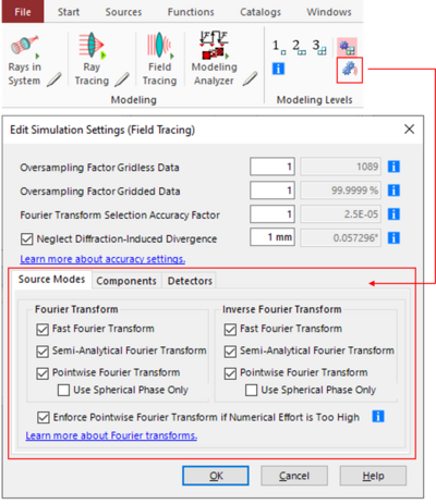
Customized Modeling
For more experienced users we provide Customized Modeling.
The selection of different Fourier transforms can be selected for source modes, the fields at components, and at detectors. That enables the investigation of the effect of different configurations and a performance optimization.
The customization can be done even more specifically, by selecting the options of Fourier transforms inside components and detectors.
Physical optics modeling with Level 1 is close to ray optics when the field information is skipped and the positions of sampling points, which are ray positions in ray optics, and the local normal vector of the wavefronts, which are the ray directions in ray optics, are considered together with the wavefront phase, which includes the aberrations.
VirtualLab Fusion provides this ray optical modeling via Ray Tracing modeling.
All detectors, which come with a ray optical definition, are evaluated. Others show the dot diagram only.
Ray Tracing
Physical optics modeling in Level 1 is close to ray optics when the field information is skipped and the positions of sampling points, which are ray positions in ray optics, and the local normal vector of the wavefronts, which are the ray directions in ray optics, are considered together with the wavefront phase, which includes the aberrations. VirtualLab Fusion provides this ray optical modeling via Ray Tracing modeling. All detectors, which come with a ray optical definition, are evaluated. Others show the dot diagram only.
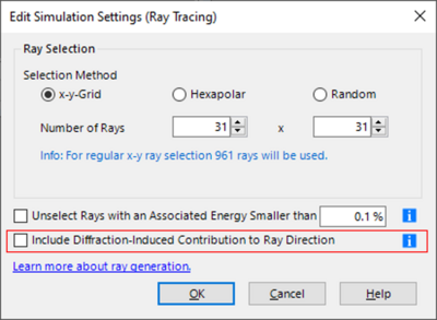
Ray optical modeling can be also displayed by the rays in the system via Rays in System.
Since ray optics is deduced from Level 1 modeling, it is consequent, that also in ray optics we have a feature which is related to the option Diffraction of Source Models Included. It is called Include Diffraction-Induced Contibutionto Ray Direction. The source mode diffraction has a direct consequence on the ray directions. For more information see <u class="BCX2 SCXW267798641 TextRun Underlined" data-contrast="none">Generation of Rays for Ray Tracing</u>.
Recommended Modeling Workflow
It should be mentioned that all techniques provide a full non-sequential modeling which can be configured according to your needs. You build the system once and sequential to fully non-sequential ray and physical optical modeling can be applied at your choice. With the different modeling options, VirtualLab Fusion provides a unique modeling workflow:
- Setup your system with sources, components, and detectors.
- Evaluate your system with Rays in System. That gives you a first modeling impression and shows you if the configuration of the system is correct and reasonable. Here you can already try the option Include Diffraction-Induced Contribution to Ray Direction.
- Next perform a Ray Tracing modeling to get a next insight into the system behavior and as a first check if detectors are at the right positions.
- It is consequent to continue with Field Tracing Level 1 modeling to get the initial physical optics results.
- Field Tracing Level 2 provides accurate modeling results for most optical systems, including lens systems. If level 1 and level 2 modeling yield the same results, diffraction of the fields which propagate to the detectors are negligible.
- By using Field Tracing Level 3, VirtualLab Fusion includes all diffraction effects where needed. The more the modeling result of this level differs from level 1 modeling, the more diffraction effects are important in the modeling of the system.
- Finally, you may customize the field tracing configuration to get a deeper insight into the effects and to optimize the performance. The more pointwise Fourier transforms are preselected, the faster is the modeling.
- If your modeling is configured well, you may combine it with Parameter Run and Optimization tools for your system investigation and optimization.
- Z. Wang, O. Baladron-Zorita, C. Hellmann, and F. Wyrowski, ‘Theory and Algorithm of the Homeomorphic Fourier Transform for Optical Simulations’, Optics Express (2020); https://doi.org/10.1364/OE.388022
- O. Baladron-Zorita, Z. Wang, C. Hellmann, and F. Wyrowski, ‘Isolating the Gouy Phase Shift in a Full Physical-Optics Solution to the Propagation Problem’, J. Opt. Soc. Am. A 36, 1551-1558 (2019); https://doi.org/10.1364/JOSAA.36.001551
- L. Yang, I. Badar, C. Hellmann, and F. Wyrowski, ‘Light shaping by freeform surface from a physical-optics point of view’, Optics Express (2020); https://doi.org/10.1364/OE.392420
- Z. Wang, O. Baladron-Zorita, C. Hellmann, and F. Wyrowski, 'Generalized Debye integral', Opt. Express 28, 24459-24470 (2020), https://doi.org/10.1364/OE.397010